Jingle bells playing light-up piano keyboard
Christmas time is just around the corner and so is the next tinkering project:
it has to do something with Christmas...
it has to do something with software...
it has to do something with electronics...
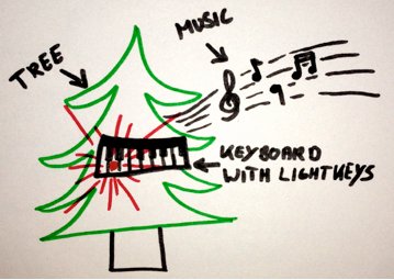
…Ermm, so the first idea was to put a bunch of colourful LEDs around a Christmas tree. Indeed, that is innovative as putting coloured paper around a gift. So I came up with the idea to make a jingle bells playing light-up piano keyboard by utilizing …well, a tree and LEDs but additionally there‘ll be a speaker ;o)
So, here‘s a little sketch about the idea:
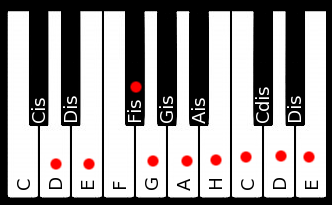
The first challenge is the keyboard design. We need to know how to play jingle bells on a keyboard. As you might know or see on YouTube tutorials, there are several ways to play this song. The easiest way is to use a single note at a time by just playing the melody of verse and chorus. The lowest key I used for playing is a D and the highest key is the E on the next octave. Between those two keys we also need E, Fis, G, A, B, C, D (on the next octave). But keep in mind, you could also transpose the melody to higher or lower notes. So, after figuring out which keys we need I started drawing a keyboard in Gimp. To make things easier, I wrote the name of the note on each key and marked the notes that have to be player with a red dot. Some more keys than necessary a there for a clean look.
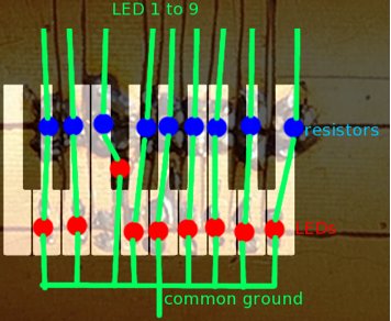
Now that we have finished the outer design of the keyboard we need the interior. There was a small non-etched copper circuit board in the tinkering box since years. So this is a good starting point. We can carve a circuit (respectively the boundaries of the tracks) into the copper board by using a box cutter. Then, soldering small SMD LEDs and resistors across the tracks (right over the cut of the box cutter) to connect them to the appropriate nets. This doesn’t only sound like a mess but it also looks like a mess.

Now let‘s put the keyboard design and some descriptions on this messy photo to see what has been done here. Since very small SMD parts were used its quite hard to see. Yes, it‘s even harder to solder. Be a little smarter than me and use bigger parts :-)
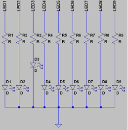
Here is an appropriate schematic design.
The next thing to prepare is a speaker. If you are lucky you find one in an old walkie talkie device, phone, toy, etc. My speaker looks like this.

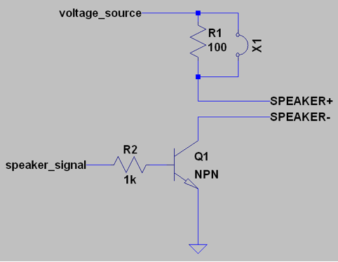
I decided to use a NPN-transistor to connect and disconnect the speaker to the voltage source. The idea is to do this with a frequency that equals the musical notes of the song. This will result in a square wave sound which is the very loud and sharp. R1 is used to make the sound more quiet. Push a jumper at position X1 to get out the maximum volume but be sure your speaker can handle the power :-)
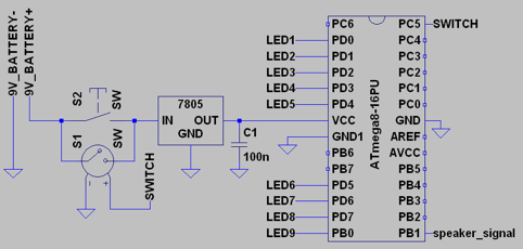
Now it‘s time to put things together. We have 9 control lines for the LEDs and 1 line for the speaker signal. We want the device to start playing if a push button is pressed and when done playing the device shall be switch off automatically. For this, we use a pushbutton in parallel to a relay switch which is controller by the ATmega. If someone presses the push button then the ATmega starts running and holds the relay closed. This way the user who pushes the button only has to hold for a few milliseconds until the system runs. If the song has been played then the ATmega shall release the relay signal so that the relay opens and the battery gets disconnected.
The electronic part is ready, now it‘s time for the software to put life inside. The song is an array of 16-bit values (uint16_t song[]) and each value represents the wave period of the appropriate piano key sound. Now, the software just has to iterate through the array, light up the appropriate LED and change the PWM settings according to the current value as read from the array. Additionally, there is a delay function for the timing to switch off the PWM between the notes to make it sound like as if the piano keys are pushed down and released in a very simple rhythm. Here is the source code.
 #define F_CPU    1000000UL

 #include <avr/io.h>
 #include <util/delay.h>

 #define C    3817
 #define CIS  3610
 #define D    3401
 #define DIS  3215
 #define E    3030
 #define F    2865
 #define FIS  2703
 #define G    2550
 #define GIS  2410
 #define A    2273
 #define AIS  2146
 #define H    2024
 #define C2   1906
 #define D2   1701
 #define E2   1515

 // jingle bells ...to me it is!
 uint16_t song[] = {
   D,  H,  A,  G, D,   0,  0,  D,  H,  A,  G,  E,  0, 0,
   E,  C2, H,  A, FIS, 0,  0,  D2, D2, C2, A,  H,  0, 0,
   D,  H,  A,  G, D,   0,  0,  D,  H,  A,  G,  E,  0, 0,
   E,  C2, H,  A, D2,  D2, D2, D2, E2, D2, C2, A,  G, 0, D2, 0,
   H,  H,  H,  0, H,   H,  H,  0,  H,  D2, G,  A,  H, 0,
   C2, C2, C2, 0, C2,  H,  H,  0,  H,  A,  A,  H,  A, 0, D2, 0,
   H,  H,  H,  0, H,   H,  H,  0,  H,  D2, G,  A,  H, 0,
   C2, C2, C2, 0, C2,  H,  H,  0,  H,  D2, D2, C2, A, G,
 };

 void play(uint16_t sound)
 {
   // sound output
   ICR1 = sound & 0xFFFE; // set period
   OCR1A = (sound & 0xFFFE) >> 2; // set pulse width

   // led output
   switch(sound)
   {
     case D:   PORTD = 0x01;  break;
     case E:   PORTD = 0x02;  break;
     case FIS: PORTD = 0x04;  break;
     case G:   PORTD = 0x08;  break;
     case A:   PORTD = 0x10;  break;
     case H:   PORTD = 0x20;  break;
     case C2:  PORTD = 0x40;  break;
     case D2:  PORTD = 0x80;  break;
     case E2:  PORTB = 0x01;  break;
     default:
       PORTD = 0;
       PORTB = 0;
       break;
   }
 }

 int main (void)
 {
   uint8_t i;
   DDRB = 0x03;  // speaker and relais are outputs
   DDRD = 0xFF;  // LED 1 to 8 are outputs
   DDRC = (1<<PC5); // LED 9 is an output
   PORTC = (0<<PC5); // keep the relais of life tight!
   TCCR1A = (1<<COM1A1) | (1<<COM1A0) | (1<<WGM11); // pwm settings
   TCCR1B = (1<<WGM13) | (1<<WGM12) | (1<<CS10);  // pwm settings

   for(i=0; i<(sizeof(song)/sizeof(uint16_t)); i++)
   {
     play(song[i]); // play note, switch LED on
     _delay_ms(200);
     play(0);    // mute sound, switch LED off
     _delay_ms(20);
   }

   PORTC = (1<<PC5);  // release the relais of life...

   return 0;
 }
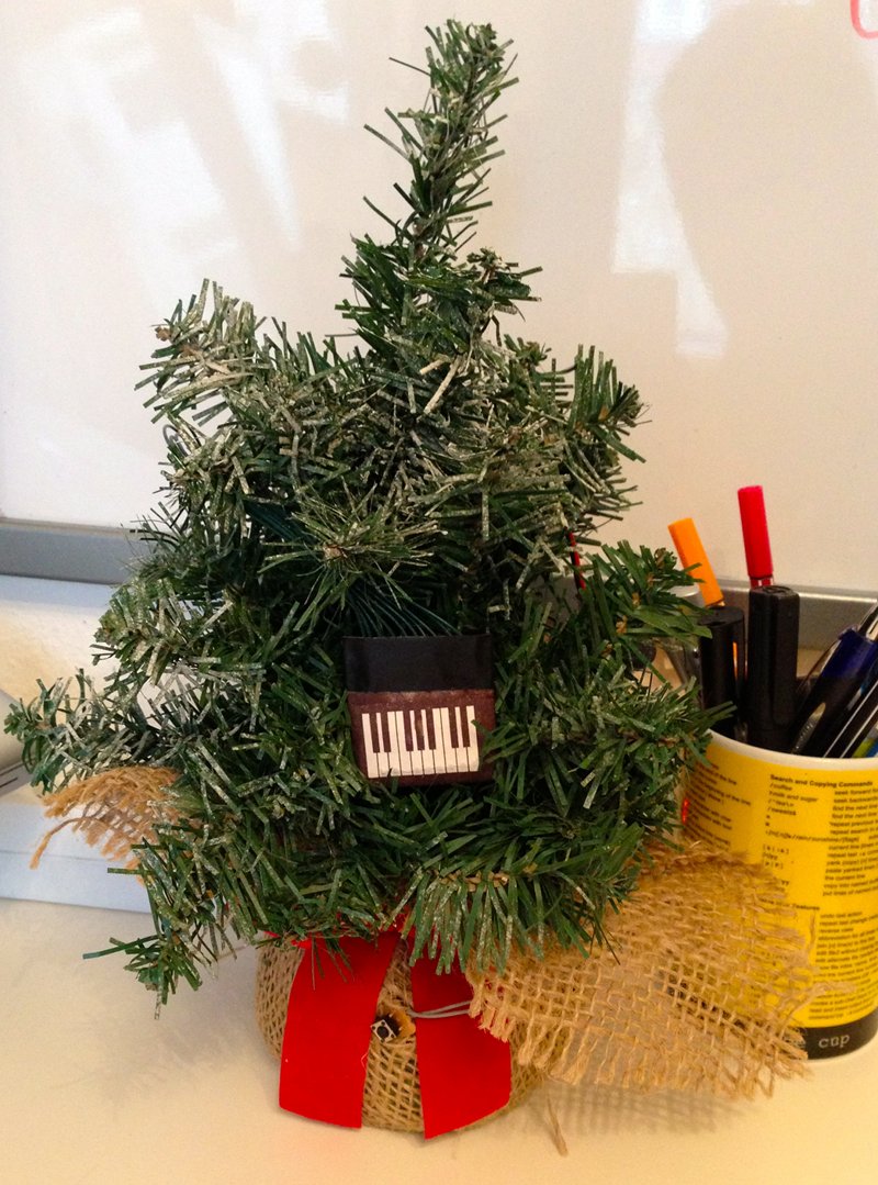
A small fake fir tree that can be found in a typical decoration store besides tons of other useless stuff makes a great stand for the keyboard and gives a real Christmas touch to it.

Now, here is my realization of the plans above. The front side shows the keyboard and a push button. The push button is at the bottom in between the red ribbon.
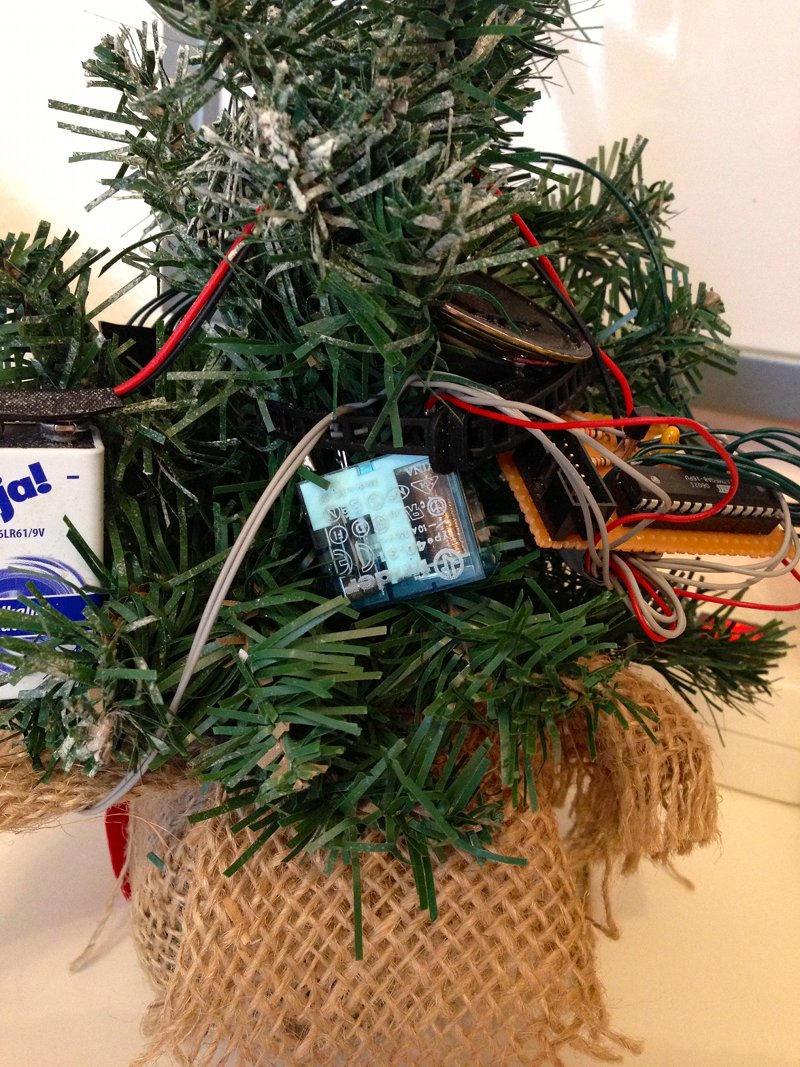
The back side shows the 9 volts battery, the speaker and the perfboard which holds the ATmega, the 7805 voltage regulator, the capacitor, the transistor and two resistors.
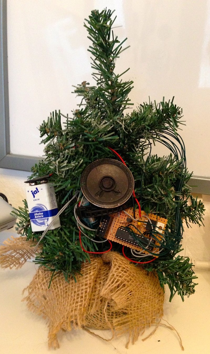
You may wonder where the relay is gone. I only had a 250V relay in my tinkering box which is kinda big. So I fixed it with a cable tie to the tree. Indeed, this is like using a sledgehammer to crack a nut but the part was already there :-)
Here is a video of the tree in action. Unfortunately, in the video it is quite hard to see that the LED illuminates one key instead of all keys nearby. This looks better in real.
